Introduction
●This section describes the main features, gives a brief functional overview of the TMS320VC5421, lists the pin assignments, and provides a signal description table. This data manual also provides a detailed description section, electrical specifications, parameter measurement information, and mechanical data about the available packaging.
●Description
●The TMS320VC5421 fixed-point digital signal processor (DSP) is a dual-core solution running at 200-MIPS performance. The 5421 consists of two DSP subsystems capable of core-to-core communications and a 128K-word zero-wait-state on-chip program memory shared by the two DSP subsystems. Each subsystem consists of one 54x DSP core, 32K-word program/data DARAM, 32K-word data SARAM, 2K-word ROM, three multichannel serial interfaces, xDMA logic, one timer, one APLL, and other miscellaneous circuitry.
●TMS320VC5421 Features
●• 200-MIPS Dual-Core DSP Consisting of Two Independent Subsystems
●• Each Core Has an Advanced Multibus Architecture With Three Separate 16-Bit Data Memory Buses and One Program Bus
●• 40-Bit Arithmetic Logic Unit (ALU) Including a 40-Bit Barrel-Shifter and Two 40-Bit Accumulators Per Core
●• Each Core Has a 17-Bit × 17-Bit Parallel Multiplier Coupled to a 40-Bit Adder for Non-Pipelined Single-Cycle Multiply/Accumulate (MAC) Operations
●• Each Core Has a Compare, Select, and Store Unit (CSSU) for the Add/Compare Selection of the Viterbi Operator
●• Each Core Has an Exponent Encoder to Compute an Exponent Value of a 40-Bit Accumulator Value in a Single Cycle
●• Each Core Has Two Address Generators With Eight Auxiliary Registers and Two Auxiliary Register Arithmetic Units (ARAUs)
●• 16-Bit Data Bus With Data Bus Holder Feature
●• 512K-Word × 16-Bit Extended Program Address Space
●• Total of 256K-Word × 16-Bit Dual- and Single-Access On-Chip RAM (128K-Word x 16-Bit Two-Way Shared Memory)
●• Single-Instruction Repeat and Block-Repeat Operations
●• Instructions With 32-Bit-Long Word Operands
●• Instructions With Two or Three Operand Reads
●• Fast Return From Interrupts
●• Arithmetic Instructions With Parallel Store and Parallel Load
●• Conditional Store Instructions
●• Output Control of CLKOUT
●• Output Control of TOUT
●• Power Consumption Control With IDLE1, IDLE2, and IDLE3 Instructions
●• Dual 1.8-V (Core) and 3.3-V (I/O) Power Supplies for Low-Power, Fast Operations
●• 10-ns Single-Cycle Fixed-Point Instruction
●• Interprocessor Communication via Two Internal 8-Element FIFOs
●• Twelve Channels of Direct Memory Access (DMA) for Data Transfers With No CPU Loading (Six Channels Per Subsystem With External Access)
●• Six Multichannel Buffered Serial Ports (McBSPs) With 128-Channel Selection Capability (Three McBSPs per Subsystem)
●• 16-Bit Host-Port Interface (HPI) Multiplexed With External Memory Interface Pins
●• Software-Programmable Phase-Locked Loop (APLL) Provides Several Clocking Options (Requires External Oscillator)
●• On-Chip Scan-Based Emulation Logic, IEEE Standard 1149-1 (JTAG) Boundary Scan Logic
●• Two Software-Programmable Timers (One Per Subsystem)
●• Software-Programmable Wait-State Generator (14 Wait States Maximum)
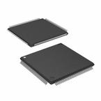
●• Provided in 144-pin MicroStar BGA™ Ball Grid Array (GGU Suffix) and 144-pin Low-Profile Quad Flatpack (LQFP) (PGE Suffix) Packages


