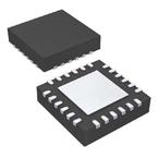
Part Datasheet Search > Logic,Standard > NXP > CBTL05024BSHP Datasheet PDF
CBTL05024BSHP Datasheet PDF - NXP
| Manufacturer: | NXP |
| Category: | Logic,Standard |
| Case Package: | 24-VFQFN Exposed Pad |
| Description: | Multiplexer/Demultiplexer Bus Switch 3Element CMOS 3IN 24Pin HVQFN |
| Documentation: | CBTL05024BSHP Application Note (21 Pages) |
| Pictures: |
CBTL05024BSHP Datasheet PDF
ADatasheet has not yet included the datasheet for CBTL05024BSHP
If necessary, please send a supplementary document request to the administrator

CBTL05024BSHP Specifications
| TYPE | DESCRIPTION |
|---|---|
| Mounting Style | Surface Mount |
| Case/Package | 24-VFQFN Exposed Pad |
CBTL05024BSHP Size & Package
| TYPE | DESCRIPTION |
|---|---|
| Product Lifecycle Status | Active |
| Packaging | Tape & Reel (TR) |
CBTL05024BSHP Environmental
CBTL05024BSHP Function Overview
Overview
●The CBTL05024 is a multiplexer/demultiplexer switch chip optimized to interface the Thunderbolt/MiniDP connector with Thunderbolt systems. It supports 10.3125 Gbit/s Thunderbolt or DisplayPort v1.2 channels.
●The TB MUX is a 3 : 1 switch that selects between Thunderbolt data path and DisplayPort v1.2 side-band signals — either DDC or AUX.
●The DP MUX is a 2 : 1 switch that selects between DP ML (DisplayPort Main Link) and LS TX/RX signals. Both LSTX and LSRX are the side-band signals for Thunderbolt channel.
●This chip also includes HPD and CA_DET buffers for HPD_IN and CA_DET control signals.
●CBTL05024 is powered by a 3.3 V supply and it is available in a 3 mm 3 mm HVQFN24 package with 0.4 mm pitch.
●MoreLess
●## Features
●### TB MUX 3 : 1 switch
● This 3 : 1 switch is implemented by two cascaded 2 : 1 switches
● The first 2 : 1 10G MUX is controlled by TB_ENA, AUXIO_EN and DP_PD pins
● The second 2 : 1 AUX MUX is controlled by CA_DET signal multiplexing of the 720 Mbit/s Differential FAUX (or 1 Mbit/s AUX) and DDC (Direct Display Control) signals
● When CA_DET is HIGH, DDC path is selected
● Differential TB channel
● Low insertion loss: -1.3 dB at 5 GHz
● Low return loss: < -20 dB at 5 GHz
● Low ON-state resistance: 8 α
● Bandwidth: 10 GHz
● Low off-state isolation: -20 dB at 5 GHz
● Low crosstalk: -36 dB at 5 GHz
● Differential input voltage VID: 1.2 V (maximum)
● Differential AUX channel
● Low insertion loss: -1.1 dB at 5 MHz -1.8 dB at 360 MHz
● Low return loss: -18 dB at 5 MHz -16 dB at 360 MHz
● Low ON-state resistance: 13 α (typical) 16 α (maximum)
● Bandwidth: 3 GHz
● Low off-state isolation: -80 dB at 5 MHz -55 dB at 360 MHz
● Low crosstalk: -26 dB at 2.7 GHz
● Common-mode input voltage VIC: 0 V to 3.3 V
● Differential input voltage VID: 1.4 V (maximum)
● DDC channel
● ON-state resistor: 50 α (maximum)
● 100 kHz 3.3 V voltage swing signal
● Both AUXIO+ and AUXIO- outputs have 85 kα (∓20 %) resistors
● The 85 kα AUXIO- pull-up resistor
● The 85 kα AUXIO+ pull-down resistor is always present
●### DP MUX 2 : 1 switch
● Multiplexes between differential DP ML signal and LSTX/LSRX signals
● The DP ML (DisplayPort Main Link) runs up to HBR2 data rate of 5.4 Gbit/s
● The low speed DC-coupled signals LSTX and LSRX are 3.3 V single-ended signals that operate at 1 Mbit/s
● 5.4 Gbit/s DP-DPMLO path for DP MUX
● Low insertion loss for DP-DPMLO path: -1.2 dB at 2.7 GHz
● Low return loss for DP-DPMLO path: -15 dB at 2.7 GHz
● Low ON-state resistance for DP-DPMLO path: 9 α
● High bandwidth: 5.5 GHz
● Low off-state isolation: -20 dB at 2.7 GHz
● Low crosstalk: -25 dB at 2.7 GHz
● LS-DPMLO path for DP MUX
● Low insertion loss: single-ended insertion loss (ON) is -1.0 dB at 5 MHz
● Low return loss: single-ended return loss (ON) is -20 dB at 5 MHz
● Low ON-state resistance: 16 α (typical) for VDD = 3.3 V
● High bandwidth: Single-ended -3 dB bandwidth is 1 GHz
● Low off-state isolation: single-ended insertion loss (OFF) is -60 dB at 5 MHz
● Low crosstalk: -40 dB at 5 GHz
●### General
● The input of the HPD (Hot Plug Detect) buffer is 5 V tolerant
● HPDOUT and CA_DETOUT buffers
● CA_DET input leakage current < 0.1 µα to prevent driving the 1 Mα pull-down to a HIGH level
● Integrated LSRX buffer with 1 M pull-down resistor (R1) on the LSRX buffer input
● Integrated 8.75 kα pull-up resistor (R4) on the LSTX pin
● When AUXIO_EN = 1, TB_ENA = 0 and DP_PD = 1, the CBTL05024 is in Detect mode
● AUXIO+ and AUXIO- of the TB MUX are disabled
● LS path is selected in DP MUX
● CA_DET and HPD buffers are on
● When the CBTL05024 is in Detect mode, this chip consumes < 18 µW
● Patent-pending high bandwidth analog pass-gate technology
● Very low intra-pair differential skew (5 ps typical)
● Back current protection on connector pins (AUXIO+/-, DPMLO+/-, CA_DET and HPD pins)
● All channels support rail-to-rail input voltage
● All CMOS input buffer with hysteresis
● Single 3.3 V ∓ 10 % power supply
● HVQFN24 3 mm x 3 mm package, 0.4 mm pitch, exposed center pad for thermal relief and electrical ground
● ESD: 2000 V HBM, 1000 V CDM
● Operating temperature range -20 °C to 85 °C
show more
CBTL05024BSHP Documents
Part Datasheet PDF Search
Example: STM32F103
72,405,303 Parts Datasheet PDF, Update more than 5,000 PDF files ervery day.

